Three-phase TCR® automatic voltage regulator
Korea’s largest capacity of three-phase 600 KVA
The TCR type automatic voltage fixer was developed in November 1983 and has made many progress to this day with absolute praise and acclaim from customers. Wherever you use AVR, you can easily see Taijin Tech’s TCR-type automatic voltage regulator. Taijin Tech Co., Ltd. has won and delivered 600 KVA AVR, the largest production capacity in Korea among TCR-type production capacity. This 600 KVA AVR features automatic static circuits and state-of-the-art protective devices, which are reliable in functionality and characteristics.
Features
RMS CONVERTOR I.C for the first time in the output voltage
detection circuit The TCR type automatic voltage regulator uses (RMS Converter I·C) for the first time in Korea to realize a highly reliable and durable full effective value detection circuit.The control circuit of this product uses PI control, so the response speed is very fast, it does not exceed the normal deviation, and it greatly improves the initial temperature change.
Improvement of Digital Tab Change Problems
The traditional Digital Tap Change product is an AVR designed as a Triac control circuit with an output single-volume T/R configuration, which is very vulnerable to noise and surge on the load side, has many failures, and unstable AVR characteristics.
This TCR type is a product that completely improves the problems of digital tap change such as no heat, no noise, high efficiency, and fast speed.
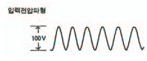
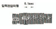
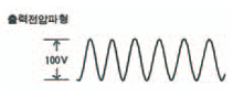
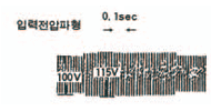
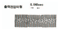
| Waveform distortion | Input voltage fluctuation characteristics | Load Variation Characteristics |
|---|---|---|
 |
 |
 |
 |
 |
 |
| Characteristics | formalities | TCR method | SCR Phase Control Method | MVR Self Amplification Control System | ||||||
|---|---|---|---|---|---|---|---|---|---|---|
| 1 | under load conditions | Good for computer analyzer inductive loads | Never used for inductive loads | Inductive load Impact load not available | ||||||
| 2 | the rate of self-waveform | not more than 3% |  |
No load | not more than 3% |  |
No load | not more than 4% |  |
No load |
 |
All of them |  |
All of them |  |
All of them | |||||
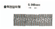
| 3 | Stability and response speed | Stability ±1% | Within 0.024 seconds | Stability ±1% | Within 0.1 second | Stability ±1% | 0.2 seconds. | |||
| Stability ±2% | Within 0.048 seconds | ±2% at load | Within 0.2 seconds | ±1% at load | 0.2 seconds. | |||||
| 4 | Efficiency | > 92% | 90% or more | 85% or more | ||||||
| 5 | Power factor (self power factor) | > ..0.95(LAG) | 0.5~0.7 | 0.4~0.6 | ||||||
| 6 | Input voltage fluctuation range | ±15% at rated voltage | ±15% at rated voltage | ±10% at rated voltage | ||||||
| 7 | Output stability (load variation) |
within ±1% | within ±1% | within ±1.5% | ||||||
| 8 | Output stability (input variation) |
within ±2% | within ±1% | within ±1.5% | ||||||
| 9 | Noise | None at all | Within 50 dB | Within 60 dB | ||||||
| 10 | Control elements and configurations | TRIAC.P.T.Resistance for power (R) | SCR, Reactor Capacitor | Control Reactor, Capacitor, Diode | ||||||
| 11 | Power consumption | 0.5A to 3A or less | 6A to 18A or less | 8A to 15A or less | ||||||
| 12 | Interference with Loads | None at all | Voltage stability, response speed, waveform | Response speed, waveform, voltage stability | ||||||
| 13 | Frequency | Available for both 50㎐ and 60㎐ | Not available for both 50㎐ and 60㎐ | Not available for both 50㎐ and 60㎐ | ||||||
| 14 | Life and failure | Semi-permanent, no fault | Control element frequently fails | Hardly, but not actually adjusted | ||||||
| 15 | High frequency generation rate | I am satisfied with the F.C.C. regulations | be full of | There’s a lot | ||||||
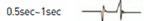
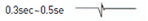
| Response Speed and a stability chart | Input voltage suddenly increases by 10%,Or when it’s Dip |  |
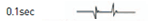 |
 |
||||||
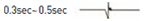
| Induction load operation |  |
 |
 |
|||||||
Use Place
TCR-type production MODEL and SIZE
| Formality | Model | Capacity | Size (mm) (W x D x H) |
|---|---|---|---|
| Three-phase TCR Type | AT 34CK | 3Ø 7.5KVA | 400 x 460 x 740 |
| AT 34CKS | |||
| AT 34CKL | |||
| AT 34EO | 3Ø 10KVA | ||
| AT 34EOS | |||
| AT 34EOL | |||
| AT 34GW | 3Ø 15KVA | 440 x 750 x 1000 | |
| AT 34GWS | |||
| AT 34GWL | |||
| AT 34IW | 3Ø 20KVA | ||
| AT 34IWS | |||
| AT 34IWL | |||
| AT 33KX | 3Ø 25KVA | ||
| AT 33KXS | |||
| AT 33KXL | |||
| AT 34MX | 3Ø 30KVA | ||
| AT 34MXS | |||
| AT 34MXL | |||
| AT 33NX | 3Ø 35KVA | ||
| AT 33NXS | |||
| AT 33NXL | |||
| AT 33Oj | 3Ø 40KVA | 600 x 900 x 1500 | |
| AT 33OjS | |||
| AT 33OjL | |||
| AT 34Pj | 3Ø 45KVA | ||
| AT 34PjS | |||
| AT 34PjL | |||
| AT 33Qj | 3Ø 45KVA | ||
| AT 33QjS | |||
| AT 33QjL | |||
| AT 34Sj | 3Ø 50KVA | ||
| AT 34SjS | |||
| AT 34SjL | |||
| AT 33Sj | 3Ø 60KVA | ||
| AT 33SjS | |||
| AT 33SjL | |||
| AT 34Uj | 3Ø 75KVA | ||
| AT 34UjS | |||
| AT 34UjL | |||
| AT 34Wn | 3Ø 100KVA | 700 x 900 x 1600 | |
| AT 34WnS | |||
| AT 34WnL | |||
| AT 33Yn | 3Ø 120KVA | ||
| AT 33YnS | |||
| AT 33YnL |
| Formality | Model | Capacity | Size (mm) (W x D x H) |
|---|---|---|---|
| Three-phase TCR Type | AT 33AN | 3Ø 150KVA | 850 X 1000 X 1800 |
| AT 33ANS | |||
| AT 33ANL | |||
| AT 34CS | 3Ø 175KVA | 900 x 1130 x 1900 | |
| AT 34CSS | |||
| AT 34CSL | |||
| AT 34FU | 3Ø 200KVA | 900 x 1130 x 1900 | |
| AT 34FUS | |||
| AT 34FUL | |||
| AT 34FU | 3Ø 250KVA | 1600 x 1200 x 1900 | |
| AT 34FUS | |||
| AT 34FUL | |||
| AT 34JU | 3Ø 300KVA | 1600 x 1000 x 2000 | |
| AT 34JUS | |||
| AT 34JUL |
* AT 3ㅁㅁㅁS는 SAFETY(산업 안전 표시) 3Ø 제품임
* AT 3ㅁㅁㅁL은 LPC(NCT 내장 AVR) 3Ø 제품임
Motion configuration diagram