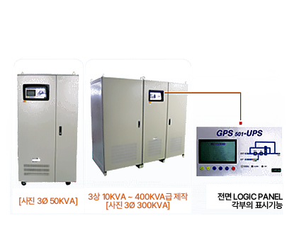
GPS®-501 Three-phase uninterruptible power supply with Type LCD function
Quietly with IGBT device control. Three-phase uninterruptible power supply GPS®-501 type, which looks bright even in the dark with advanced LCDs, uses LCD for display and allows UPS to operate even in dark installations. It’s a high-performance, high-performance product that you can check.
Overview
This product is an IGBT-type UPS manufactured using a state-of-the-art power element in a non-pure synchronous cutting method, and the rectifier on the input side consists of 6 Pulse or 12 Pulse. The inverter configuration adopts the angular phase control method so that the load ratio of each phase can be adjusted, and the operating frequency is 20㎑, so there is very little noise during operation, and it is designed to have various protection functions. When the inverter stops operating, the output power is made to power the load with a non-stop bypass power, which is detected by the micro-processor and stored automatically. In addition, the operation status of each part can be easily read by displaying the operation status in Logic, and at the same time, the LCD can check voltage, current, frequency, DC voltage, etc. with one-touch method, making it a very easy-to-operate UPS.
Features
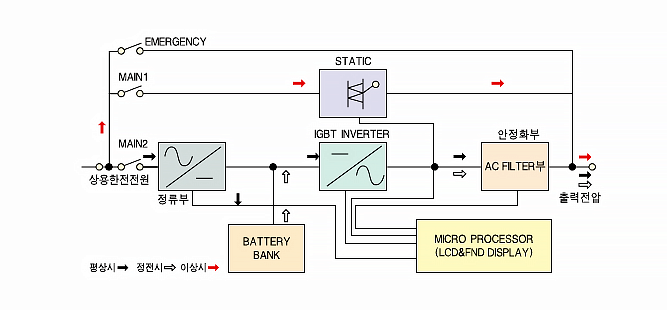
Motion configuration diagram

Operation’s description
When Main-2
is supplied – Main-2 supplies AC power to the rectifier with commercial power, and the rectifier converts the net to automatically charge the battery in case of a power failure. The inverter part consists of the IGBT Full Bridge method and detects and controls each phase, so there is no voltage deviation in the unbalance load.
Main-1
Supply – Bypass Power Supply is used as a load protection reserve during initial operation and during equipment failure and is not eligible for power failure.
EMERGENCY S/W
– This device is added to maintain the UPS without disconnecting load power in the event of an inverter failure.
In the case Overload and inverter failure – In the event of an overload, the inverter stops automatically and automatically cuts off without turning off. The auto-cutter is cut to Main1 and automatically restored to the inverter when the overload condition is released.
Display Channel
– It displays all the operation-status through VFD and switches between Invertor On/OFF mode.
– Automatic rectifier-part
– Synchronous switching part
– Battery part
– Three-phase inverter part
– VFD Display part
– Maintenance part
GPS-501 Configuration Diagram
GPS-501 Type
UPS + Battery + Battery Protection Case + LCD Features
Battery + Battery Protection Case + LCD Features
PUSH BUTTON S/W Display each function
It shows operation-status of each part.
LCD adoption (front indicator)
– Through LCD system, each part’s operation status is clearly shown.
– Operation status can be checked continuously through key manipulation.
Standard Specifications and Characteristics
| Capacity (VA) | 10K~30KVA | 40K~75KVA | 100K~150KVA | 200K~250KVA | 300K~400KVA |
|---|---|---|---|---|---|
| Standing history | |||||
| Number of constants | 3 phase 4 wire | ||||
| Input voltage | 380V AC±10%(standard) | ||||
| The number of waves | 60㎐ ±5% | ||||
| DC voltage | 264V DC | 396V DC | |||
| Dispatch peculiarities | |||||
| Number of constants | 3 phase 4 wire | ||||
| Output voltage | 380V AC(standard) | ||||
| Anjeongdo | ±2% | ||||
| Waveform | Sine wave type | ||||
| Control method | IGBT(PWM control) | ||||
| Why Yule | ±3%(at linear load) | ||||
| Load power factor | 0.8(ground) | ||||
| Overload tolerance | 125% – 10minutes / 150% – 1minute | ||||
| Cattle | Within 55dB | Within 60dB | Within 65dB | Within 70dB | Within 75dB |
| Load Balancer | Load Factor 50% – 2% | ||||
| Load Factor 100% – 3% | |||||
| Efficacy | > 85% | > 90% | |||
| Discipline | |||||
| Number of constants | 3 phase 4 wire | ||||
| The number of waves | 60㎐ | ||||
| Overload tolerance | 150% – 1 minute | ||||
| Cut-off time | Within 4ms | ||||
| Absolute conditions | Battery voltage / overload / overtemperature / equipment failure / manual stop | ||||
| Ability | |||||
| Kick short-term | Input/output/battery/maintenance | ||||
| Display function | nput, output voltage/current/frequency, accumulator voltage, inverter ON/OFF, alarm stop system history and failure history storage |
||||
| enclosure | |||||
| Size(main body)(W×D×H) | 600×700×1400 | 800×700×1400 | 1000×850×1700 | 1600×1000×1800 | 2000×1000×1900 |
* 본 size는 품질 향상을 위한 설계 변경 과정에서 다소 달라질 수 있습니다.


